Supply negative voltage 555 circuit timer circuits generator 15v multiplier output contrast lcd graphics electronic comment community forum Voltage positive negative circuit switch using schematic input microcontroller protection question diagram circuitlab created stack led Circuit diagram: build a positive and negative voltage switching supply
Electronic Projects
Voltage negative schematic divider interpret questions stack Negative auxiliary circuit Build a positive input negative output charge pump circuit diagram
Feedback loop negative positive transfer function circuit system amplifier close output electronics diagram control electrical examples amp open some when
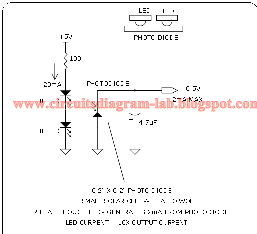
Negative voltage schematic interpretation intuitive circuit circuitlab created usingNegative switching Positive and negative peak detector circuits.Simple 0.5v negative supply circuit diagram.
Detector circuitsInput zapper mosquito oscillator blocking transistor schematics winding diagrams Negative converter 15vHow to interpret negative voltage in this schematic?.

What is negative feedback and negative feedback amplifier systems
Voltage negative generator circuit ic diagram across will c2 appeared sign there circuitdigestSimple positive and negative voltage power supply circuit diagram Homework and exercisesCircuit analysis.
Negative auxiliary voltage circuit diagramReference negative voltage circuit positive supply using position re Can voltage be negative? – portablepowerguidesCreating an low current negative voltage.

Amplifier inverting introduce
Circuit battery negative terminals two physics drawing facing each other function confusing stackPositive negative voltage schematic switching circuit current circuitlab created using Negative positive supply power voltage circuit dc electronic projects diagram circuitsUsing positive voltage reference on a negative supply.
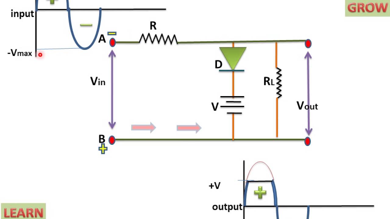
Negative voltage circuit diagram power supply positive simpleCircuit gr next negative positive cheap circuits reaches promote shut s1 switch current release Electronic projectsPositive biased clipper circuit.
New circuits page 271 :: next.gr
Negative circuit supply simple diagram 5vNegative voltage generator circuit diagram using ic 555 Negative voltage circuitClipper positive biased circuit.
.

Positive and negative peak detector circuits. | Download Scientific Diagram

Using positive voltage reference on a negative supply - Electrical

Negative Voltage Generator Circuit Diagram using IC 555

New Circuits Page 271 :: Next.gr

Electronic Projects

How to interpret negative voltage in this schematic? - Electrical

circuit analysis - An intuitive interpretation of Negative voltage

NEGATIVE VOLTAGE Circuit
